After a period of sporadic
P1120 and
P1516 DTC's and not being able to push WOT without these DTC's with entering reduced power mode, I decided to go to the bottom with the problem. My setup is a 87mm truck TB mounted vertically on a Holley EFI intake manifold. The engine, ECU and TAC module is LS1 from a Corvette 1998. After lots of investigation I came to the conclusion that the TB was not compatible with my TAC module even though the TPS signals were within the expected limits that could be found by Google:ing around for a while. Some experiments with manipulating the TPS sensor signals showed that this was the case.
I contacted Torque Rush regarding their X-Link product and they
confirmed that this incompatibility is a fact and that they, at the moment
don't have any solution for this setup. Going for a LS2 or LS1 throttle body is not an option since this is the only alternative that fits to the adapter kit and the manifold I have. The solution was to build an interface (type X-Link) that emulates the TPS values from an LS1 throttle body. I didn't succeed to find the exact specs for TPS values on Internet so I measured on a stock LS1 throttle body and on my new 87 mm truck throttle body. The LS1 TB goes from 0.4 to 4.6V on TPS1 and vice versa on TPS2 while truck TB on the other hand goes from 0.65 to 4.4V.


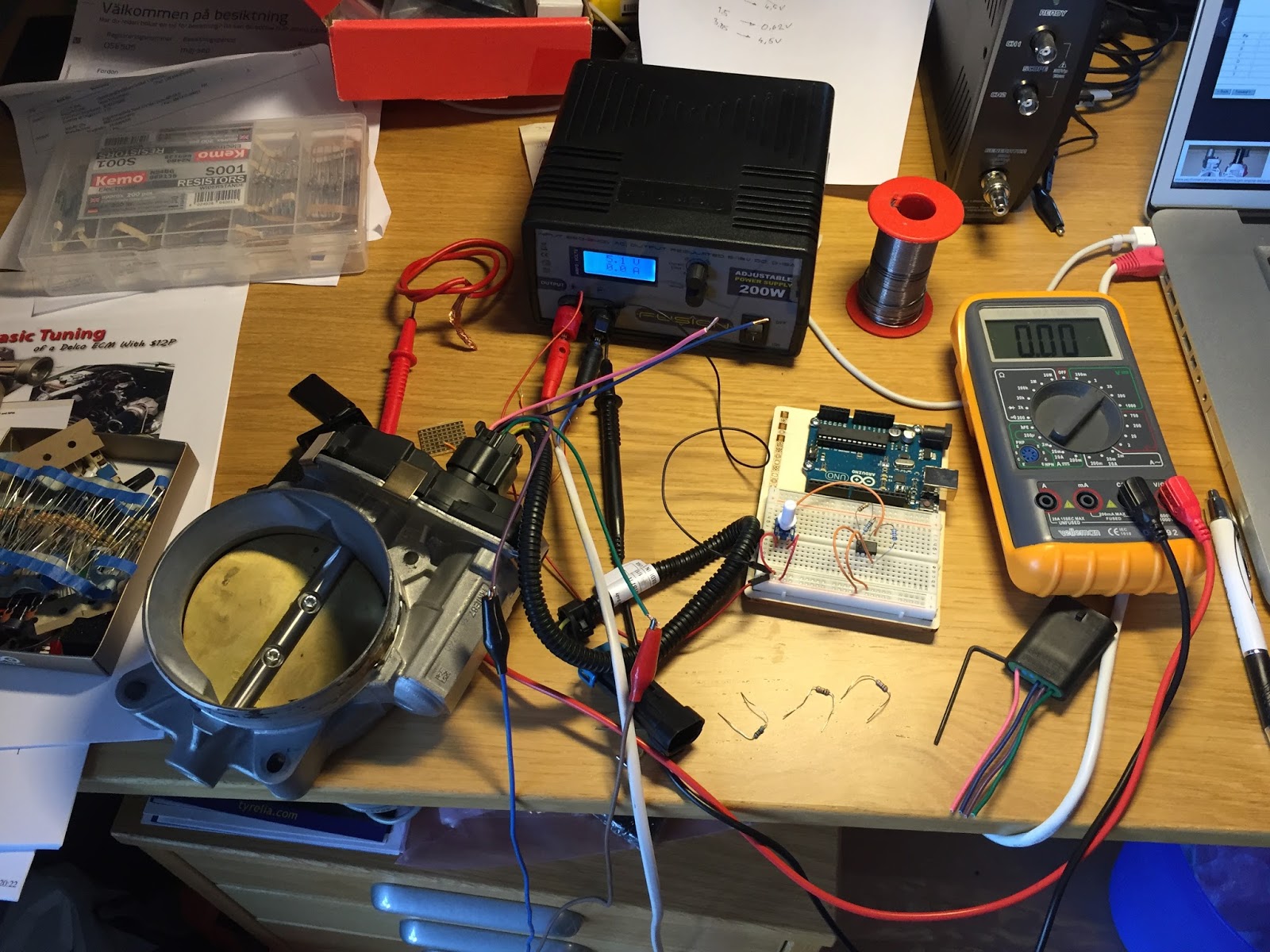
The trick is to create a DC amplifier with a gain of (4.6 - 0.4) / (4.4 - 0.65) = 1.12. The amplifier must also transpose the DC levels down a bit. This circuit must be duplicated, one for each sensor and have the capabilities to swing the output almost rail-to-rail since we only have the 5V reference from the TAC module as supply voltage. Luckily there is a dual operational amplifier from National Semiconductors, LMC6482, that suits perfect for this task.
It is a small 8-pin circuit which makes it possible to build it as a dongle on the throttle body cable.
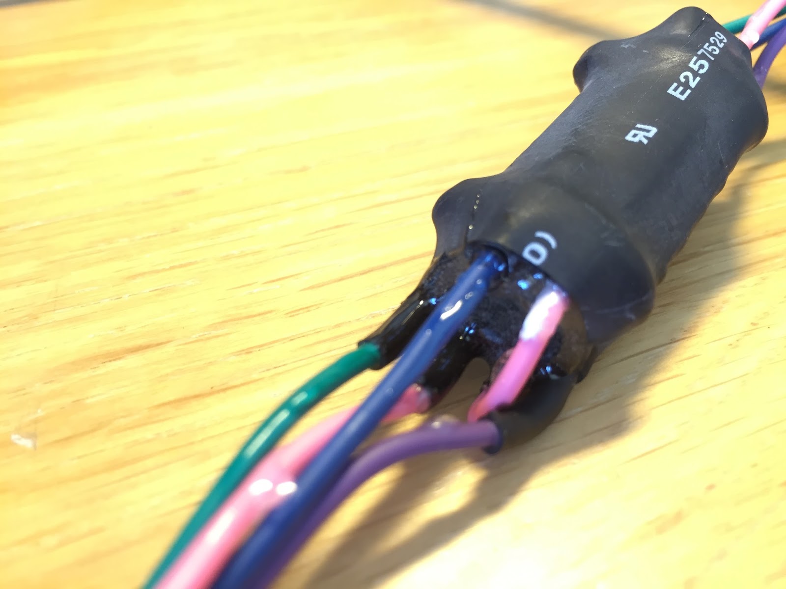
The circuit was built on a piece of experiment PC board that was cast in epoxy to withstand humidity and mechanical damage.
A final shrink tube covers the circuit and sealing both ends with epoxy makes it absolutely water resistant.
The complete harness with the interface dongle looks like this. Ready to plug in!


Inga kommentarer:
Skicka en kommentar